On
the day of our public presentation, we were able to successfully blend
smoothies for all of our customers! The ingredients we blended included:
strawberries, bananas, mangoes, raspberries, yogurt, and fruit juices.
The blending apparatus was able to function hands-free, so the process
only required one person, who was pedaling the bike. This met our design
specifications in that it was hands-free and blended fruits.
Furthermore, our blending attachment is detachable from the bike and can
be adjusted to fit on bikes with differing rear rack arrangements.
Future testing would include blending beans, though we expect our
blender to do this easily. We had successful blends when the pitcher had
only a small amount of contents in it, and also when it was completely
full. Each round of smoothies only took about 30 seconds to 1 minute to
make, depending on how much fruit was in the pitcher and how full the
pitcher was. People were attracted by our project, and after hearing
about our design and construction process, they got to walk away with a
refreshing smoothie! (Some people even blended their own!)
In
terms of follow-up with Grupo Fenix, we have sent them our final
documentation, pictures, videos, and instruction manual. We expect to
discuss our design with them this week.
As
for the future, we hope to develop a working prototype of our stand
design. In addition, our current design will need to be tested on
different bikes. Through further testing, we hope to improve the ease
with which we attach the blender attachment to the rear rack, as well as
the structural integrity of the blending apparatus (specifically the
rubber wheel and the blade). 

One of the goals of our project this semester was to document the steps we followed and materials we used to create a working bicycle-powered blender. By an instruction manual, we hope future groups can spend the majority of their efforts improving an existing design rather than figuring out how to simply create a working blender.
Instruction Manual
Making the Blender - Materials
1 pitcher with top
1 plastic water bottle top (cap and neck)
1 plastic rod (~ 1/3 inch in diameter) ( ~ 1.75 inches in length)
1 metal bar (~0.06 inches in diameter)
1 0.625 inch steel plated ball bearing
1 circular piece of rubber with a hole in it to fit around the plastic rod
1 piece of thick sheet metal
strong piano wire
~0.06 inches in diameter
~ 2 inches in length
epoxy glue
Making the wheel attachment / base - Materials
1 complete front bike axle including:
1 piece of bike tire (or any form of rubber) ~1.25 feet long, to make a wheel that is ~1.7 inches in diameter
screw eye hooks,
screw length 0.3 inches, can be longer, but shouldn’t exceed 0.5 inches
hook diameter 0.2 inches, can be larger or smaller
1 wood platform (L x W x H) = ~(9.25in x 5.75in x 0.75in)
1 wooden donut
outer diameter 4.6 in (does not have to be specific)
inner diameter 1.84 in (needs to be specific, must match the diameter of the flanges on the hub shell)
2 screws ~0.1 inch in diameter
2 aluminum standoff 6-32 x ¾”, ¼” round
Procedure:
Making the blender:
 |
| Cut the bottle cap at the red line |
1.
Find water bottle and cut off top including cap (make cut about ½ inch
below the base of the cap, or at the location where the bottle starts to
curve outward)
2.
With cap removed, place ball bearing such that the bearing fits snugly
inside of the cap (it may be necessary to sand the inner plastic in
order to have a tight fit).
3. Drill a hole through the cap that is slightly larger than the diameter of the plastic rod
4. Screw cap onto bottle neck/ball-bearing piece.
 5. Drill a small hole through the plastic rod (approximately 0.06 inches in diameter) approximately 2 mm away from either end.
6. Insert midsection of nail into one of the small holes.
7.
Insert rod through hole in ball bearing fitted in bottle neck such that
the nail is at the bottom of the bottle’s neck. The nail should not
touch the edges of the bottle cap when rotated (trim as necessary).
 8.
Cut out rubber washer with an outer diameter that matches the diameter
of the bottle cap, and an inner diameter that is slightly smaller than
the diameter of the plastic rod (so that it fits snugly). Place this washer such that it rests on the bottle cap.
8.
Cut out rubber washer with an outer diameter that matches the diameter
of the bottle cap, and an inner diameter that is slightly smaller than
the diameter of the plastic rod (so that it fits snugly). Place this washer such that it rests on the bottle cap.
9. Insert approximately 2 inches of piano wire into other small hole that is above the bottle cap/ rubber washer.
10.
If the rod moves vertically, carefully apply a thin layer of epoxy glue
to the inner side of the ball bearing. Ensure that the ball bearings
can still freely rotate.
11. Glue the rubber washer with epoxy glue to the top of the bottle cap.
12. Obtain a a 1 in x 5 in x .03 in (or slightly larger) piece of sheet metal.
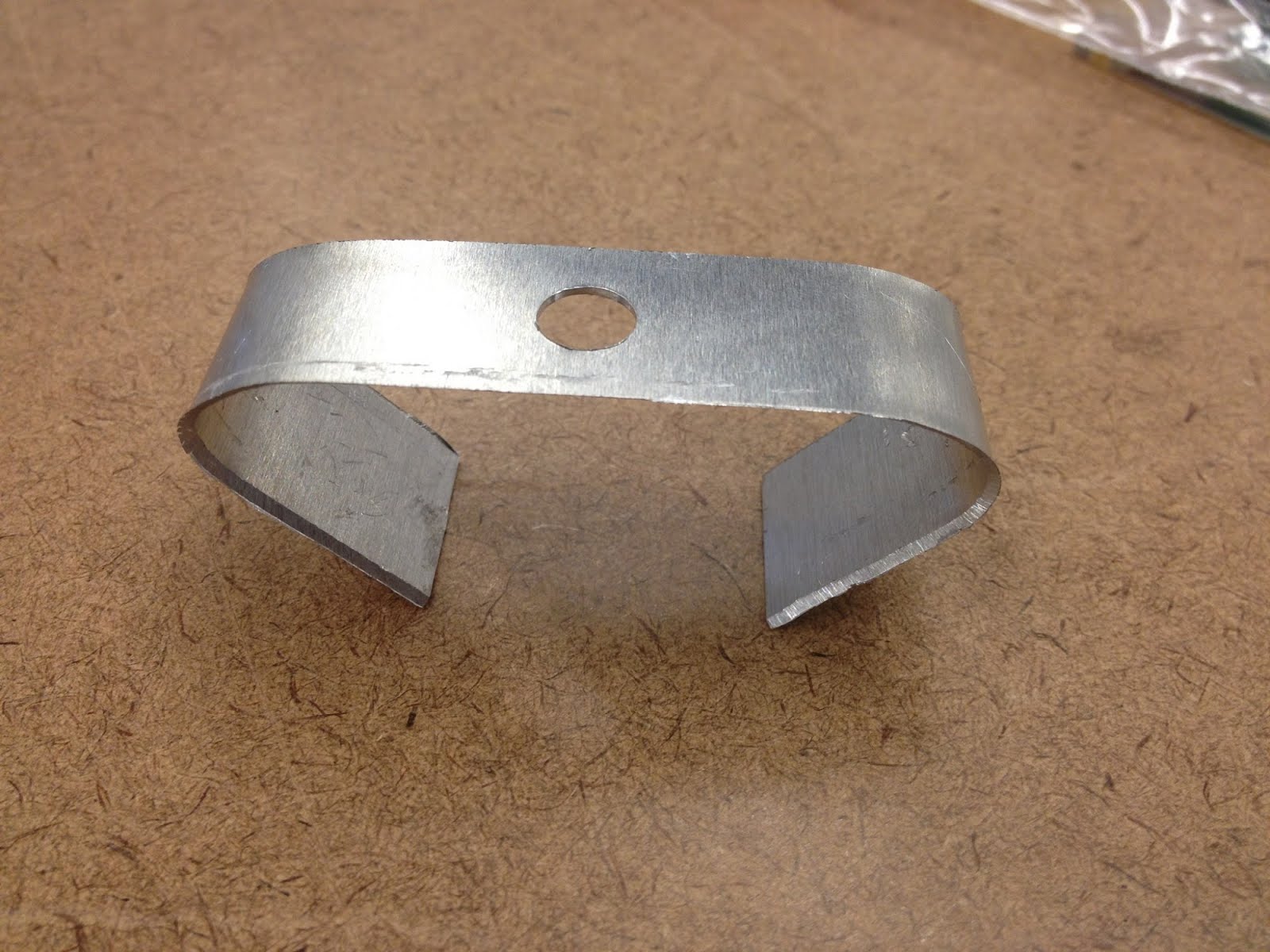 13. Drill a hole of the same diameter as the plastic rod in the center of the metal piece.
14. Sharpen the length of the blade on both sides by sanding the edges.
15. Using a rounded surface, gently bend each end of the metal piece into a c-shaped curl (refer to blade
picture).
 16. Place blade, with c-shaped curl facing down, on plastic rod and allow it to rest on the piano wire.
17.
Bend the piano wire around the top of the blade so that it is hugging
the top of the blade. The blade should not move independently of the
rod.
18.
Using a step drill bit, drill a hole in the center of the bottom of the
pitcher that matches or slightly exceeds the diameter of the bottle
neck.
19. Apply a thin layer of epoxy on the bottom of the lip of the bottle.
 20. Insert the bottle cap/blade piece into the hole at the bottom of the pitcher. Allow glue to set.
Making the wheel axle:
1. Remove lock nuts on one end of axle.
2.
Make a slit at one end in the 1 foot long piece of rubber and insert
the axle through this slit. Refasten lock nuts to the axle such that
they are on either side of the rubber.
3.
At the other end of the axle, remove both lock nuts. Cut rod such that
the top of the axle is approximately 1/4 of an inch below the top of the
bottom nut (the one that sits closer to the ball bearings). Reattach
bottom nut.
4.
Using a dremel tool (or a hand saw), cut a channel through the middle
of the nut (along the diameter) such that the nail used in the plastic
rod can sit in the wedge:
5.
Fully extend the length of rubber and flatten such that there are two
distinct sides. Apply epoxy to one side and tightly wrap the full length
of the rubber around the lock nuts, forming a wheel. Clamp the wheel in
this arrangement until the epoxy dries.
Securing blender and wheel axle to rear rack of bike:
 1.
Insert axle to rear rack such that rubber wheel sits against the middle
of the bike’s rear tire . It may be necessary to cut a hole in the rear
rack in order to fit the axle through.
1.
Insert axle to rear rack such that rubber wheel sits against the middle
of the bike’s rear tire . It may be necessary to cut a hole in the rear
rack in order to fit the axle through.
2. While the axle is correctly positioned (step 1), cut U channel in wood platform so the axle can rest in the channel.
 3. Secure axle to channel using approximately 5 eye screw hooks.
4. Next, prepare the wooden donut to support the blender with correct dimensions.
5.
With the wooden platform- wheel axle arrangement aligned correctly,
insert 2 screws on the opposite side of the wooden platform such that
they rest against the outer rim of the rear rack. Once screws are
inserted, place aluminum standoffs on the screws.
6.
Wrap two small bungee cords, positioned on both sides of the wheel
axle, around the rear rack to secure the platform in place.
7.
Fit blender in wheel axle (ensuring that the nail in the plastic rod
fits in the channel in the lock nut) and secure by wrapping a large
bungee cord from one side of rear wheel axle to the other side of the
rear wheel axle, making sure to pass the bungee cord over the top of the
pitcher as seen in picture A
 8. Hop on the bike, blend, and enjoy the fruits of your labor!
 |
| PICTURE A |


